grandis principle
At the same time our controllers are flexible enough to meet requirements of any kind!
How do we manage that?
Our controllers are designed on the basis of a modular principle – they are comprised of modules that are perfectly tailored to one other.
What is a multi-functional controller?
![]()
- Every free output of a Prozeda controller can be programmed with an additional function in a fast and easy way (also the free outputs of flex 400 when connected to grandis 650 HK). We call these additional functions Multi-Functional Controllers (MFR).
An MFR extends the pre-defined hydraulic layouts in a very flexible way.
- Depending on a controller type there are up to 20 different multi-functional controller types available. The modular structure of this approach allows hundreds of combinations and can solve even very complicated tasks.
Temperature difference controller
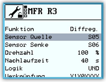
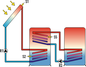
The Temperature difference controller is the most widely used function. There is a measurement point at both the source and the sink. If the difference between the temperatures of the two measurement points exceeds a predefined value, the switching output of the multi-function controller switches on.
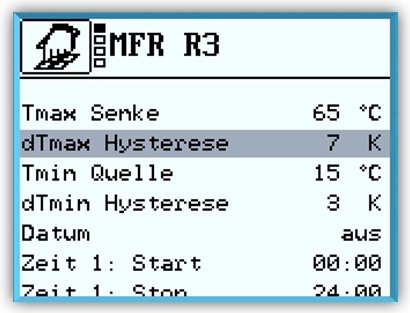
In addition, a minimum temperature can be set at the source and a maximum temperature at the sink. If the maximum temperature is exceeded or the temperature falls below the minimum temperature, the switching output of the multi-function controller switches off.
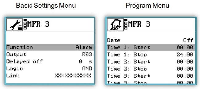
Activate Settings
Examples
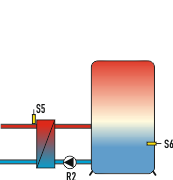
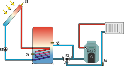
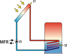
Reloading

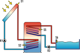
Output: R3, Source: S5, Sink: S6
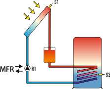
External heat exchanger
Output: R3, Source: S5, Sink: S2
Pool
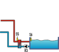
Output: R2, Source: S3, Sink: S4
Pool with external heat exchanger
Output: R4, Source: S5, Sink: S6
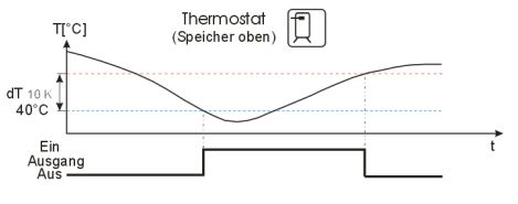
Heating
Simple thermostat function. The switching output of the multi-function controller switches on as soon as the temperature falls below the preset switch-on temperature. If the temperature rises above the upper limit of the preset temperature range (hysteresis), the switching output of the multi-function controller switches off..
Typischer Ablauf
Example
Re-heating

Output: R2, Source: S5
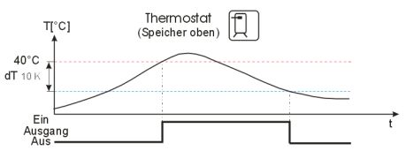
Cooling
Simple thermostat function. The switching output of the multi-function controller switches on as soon as the preset switch-on temperature is exceeded. If the temperature drops below the lower limit of the preset temperature range (hysteresis), the switching output of the multi-function controller switches off.
Typischer Ablauf
Examples
Cooling
Output: R3, Source: S5
Re-load
Output: R3, Source: S5
Threshold value switch
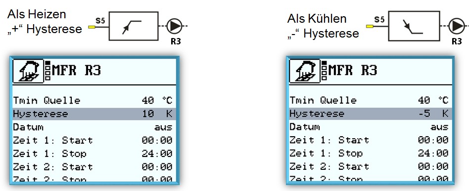
As a flexible option of the functions heating and cooling. the switching output of the multi- function controller switches on as soon as the temperature reaches the preset switch-on temperature. If the temperature drops below or rises above the preset temperature range (hysteresis), the switching output of the multi-function controller switches off. To use this function for heating, set the “Hysteresis” value to greater than 0. To use this function for cooling, set the “Hysteresis” value to less than 0..
Wood-fired boiler
This function allows you to re-heat the storage tank from a solid fuel boiler. The switching output of the multi-function controller will be activated if the boiler temperature (source sensor) plus the selected temperature range (hysteresis) exceeds the storage tank temperature (sink sensor).
In addition you can also define a switch-on temperature (setpoint temperature). In this case the pump will not start until the switch-on temperature has been reached. With this function the storage tank will be heated to a maximum temperature of 95 °C.
Example
Tipical re-heating
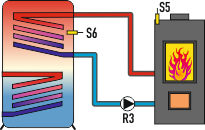
Output: R3, Source: S5, Sink: S6
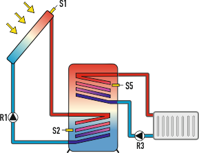
Example
Return line boost
Output: R3, Source: S3, Sink: S4
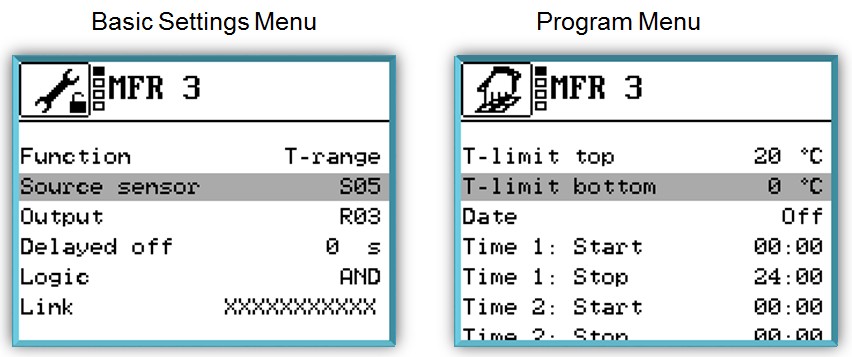
Circulation – temperature-controlled
The switching output of the multi-function controller switches on as soon as the temperature falls below the preset setpoint temperature. If the temperature rises above the upper limit of the preset temperature range (hysteresis), the switching output switches off.
Example
Temperature-controlled Circulation
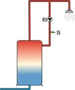
Output: R3, Sink: S6
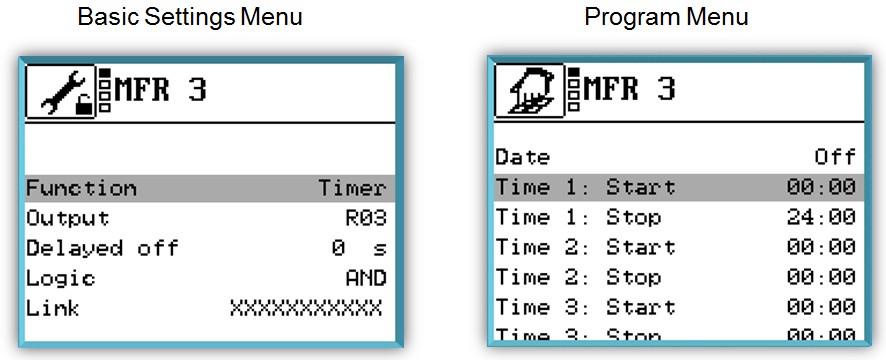
Example
Time-controlled Circulation
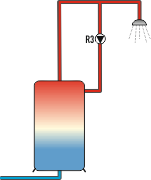
Output: R3
Example
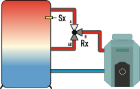
Warm water re-heating
Solar boost (only grandis 600 SR)
With this function, the switching output of the multi-function controller is linked either to the solar control or to the “drain-back” function. If the solar control or drain-back function is active, the MFC will be switched on, and at the end of the adjustable runtime it will be switched off again. If the solar control is switched off during this time, the MFR will also be switched off. For the MFC to react again when switched on, the solar power system must be continuously off for at least a selected off period.
Linking is possible to:
Solar control
Drain Back
Solar redundancy (only grandis 600 SR)
If a flow fault is reported during this function, the switching output of the MFC will be switched on and it will run in parallel with the solar power system. If the flow fault is rectified within the specified runtime, the link will be cancelled and the MFC will stop. If the flow fault still exists when the runtime has ended, the MFC will be permanently linked to the solar power system. This will be indicated by a fault message. You can use “Reset” to reset the permanent link to the solar power system. This will also reset the fault message.
Solar redundancy
Mischer
Mit dieser Funktion können Sie eine Rücklaufanhebung mittels Mischer auf die berechnete maximale Vorlaufsolltemperatur der Heizkreise realisieren. Der Multifunktionsregler benutzt als Referenz je nach Einstellung die Heizungsvorlauftemperatur, die Warmwassersolltemperatur oder eine einstellbare Soll-Temperatur.
Beispielanwendung
Rücklaufanhebung mit Referenz die aktuell höchste Vorlaufsolltemperatur. Regeltemperatur „Heizen“ und Regelmodus “Vorlauf mit Freigabetemperatur”.
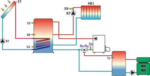
Der Mischer wird abhängig vom Sensor Quelle (Sy) und Sensor Senke (Sx) geregelt. Überschreitet die Quelle die Vorlaufsolltemperatur + Hysterese, ist die Funktion aktiv und der Mischer regelt auf die Vorlaufsolltemperatur + Hysterese.
Eine einstellbare Zieltemperatur als Referenz. Regeltemperatur „Festwert“ und Regelmodus “Rücklauf mit Freigabetemperatur”.

Der Mischer wird abhängig vom Sensor Quelle auf eine feste Zieltemperatur geregelt. Unterhalb der Zieltemperatur wir der Mischer zugefahren.
![]()
Our service for you
At Prozeda, we work hand-in-hand with our solar and heating systems installer partners in order to provide them with the best possible solutions. As a special service we offer configurations of example systems.
You can download the parameter files, you can use them as they are, or modify them according to your needs. And you can of course use the layouts for you conexio 200. Wie genau das geht, sehen Sie in unseren Kurz-Anleitungen:
Please note, that the following system layouts parameter settings for grandis 650 HK V2.00.26. They are not to be understood as a complete hydraulic circuit diagrams and are only example layouts.
Also, you must verify all settings and parameters carefully before applying in real systems..
1 heating circuit with hot water processing + solar
Layout 110.00 + 1 mixed heating circuit
- 1 solar circuit (1 collector - 1 storage tank), PWM pump with minimum speed control 30%.
- 1 mixed heating circuit, linear heating curve. Hot water function.

Settings: PS291404
Record: 19-12-02.txt
1 heating circuit with hot water processing + solar + wood-fired boiler
Layout 110.00 + 1 mixed heating circuit + wood-fired boiler
- 1 solar circuit (1 collector – 1 storage tank), both PWM pumps with minimum speed control 30%.
- 1 mixed heating circuit, linear heating curve. Hot water function
Wood-fired boiler over Multi-function controller.

Settings: PS291445
Record: 19-11-29.txt
1 mixed + 1 unmixed heating circuits with hot water processing + solar
Layout 111.00 + 1 mixed + 1 unmixed heating circuit
- 1 solar circuit (1 collector – 1 storage tank), both PWM pumps with minimum speed control 30%.
- 1 mixed heating circuit, linear heating curve. Hot water function. 1 unmixed heating circuit.
HW reheating with 3-way valve

Settings: PS021001
Record: 19-12-02.txt
1 mixed heating circuit+Wood-fired boiler.
- 1 mixed heating circuit, linear heating curve. No hot water function.
- Wood-fired boiler over Multi-function controller.

Settings: PS021009
Record: 19-12-02.txt
1 mixed + 1 unmixed heating circuits with hot water processing + solar
Layout 111.00 + 1 mixed + 1 unmixed heating circuit
- 1 solar circuit (1 collector - 1 storage tank), both PWM pumps with minimum speed control 30%
- 1 mixed heating circuit, linear heating curve. Hot water function
- 1 unmixed heating circuit
- HW reheating with 3-way valve.

Settings: PS021141
Record: 19-12-05.txt
2 heating circuits with hot water processing + solar
Layout 110.00 + 2 mixed heating circuits
- 1 solar circuit (1 collector - 1 storage tank)
- 2 mixed heating circuits, linear heating curve. Hot water function.

Settings: PS021146
Record: 19-12-06.txt
2 heating circuits with hot water processing + solar + wood-fired boiler
Layout 110.00 + 2 mixed heating circuits + wood-fired boiler
- 1 solar circuit (1 collector - 1 storage tank), PWM pump with minimum speed control 30%
- 2 mixed heating circuits, linear heating curve. Hot water function with pump

Settings: PS021208
Record: 19-12-07.txt
2 heating circuits with hot water processing + solar with 2 storage tanks + wood-fired boiler
Layout 210.01 + 2 mixed heating circuits + wood-fired boiler
- 2 solar circuits (1 collector - 2 storage tanks), PWM pump with minimum speed control 30%
- 2 mixed heating circuits - one of them with flex module flex 400 or Hydroflex module, linear heating curve. Hot water function with pump

Settings: PS021216
Record: 19-12-08.txt
2 heating circuits with hot water processing + solar with 2 storage tanks + wood-fired boiler
Layout 210.01 + 2 mixed heating circuits + wood-fired boiler
- 2 solar circuits (1 collector - 2 storage tanks), PWM pump with minimum speed control 30%
- 2 mixed heating circuits - one of them with flex module flex 400 or Hydroflex module, linear heating curve. Hot water function with pump

Settings: PS021236
Record: 19-12-09.txt
1 heating circuit with hot water processing + solar with pool heating
Layout 210.01 + 1 mixed heating circuit
- 2 solar circuits (1 collector - 1 storage tank - 1 pool), PWM pump with minimum speed control 30%. (Pump R3 over MFC)
- 1 mixed heating circuit, linear heating curve. Hot water function

Settings: PS021240
Record: 19-12-10.txt
1 heating circuit with hot water processing + solar with pool heating
Layout 211.01 + 1 mixed heating circuit
- 2 solar circuits (1 collector - 1 storage tank - 1 pool), PWM pump with minimum speed control 30%. (Pump R4 over MFC)
- 1 mixed heating circuit, linear heating curve. Hot water function.

Settings: PS021244
Record: 19-12-11.txt